

Table of Contents
- 1. Mechanical Installation
- 2. Sensor Wiring
- 3. Bus Power and Loop Wiring
- 4. Dual-Channel Configuration
- 5. Cold Junction Compensation Setup
- 6. Field Calibration Procedures
- 7. LCD and Local Operation
- 8. Explosion-Proof Installation Requirements
- 9. Startup and Verification Checklist
- 10. Troubleshooting Quick Reference
1. Mechanical Installation
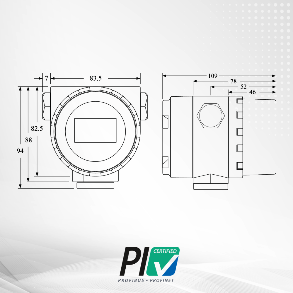
The NCS-TT105 offers three mounting bracket options. Select based on your installation location and pipe diameter.
1.1 Mounting Bracket Types
| Bracket Code | Type | Orientation | Pipe Diameter | Fastener |
|---|---|---|---|---|
| B8 | Flat bracket tube | Vertical pipe | ~Φ50 mm | U-bolt |
| B6 | Curved bracket tube | Horizontal pipe | ~Φ50 mm | U-bolt |
| B7 | Curved bracket plate | Wall / panel | N/A | M10 bolt (user-supplied) |
1.2 Installation Steps
Step 1: Secure the transmitter to the bracket
Use the four M4 bolts (provided) to attach the transmitter body to the bracket. Torque to standard industrial specification.
Step 2: Mount to pipe or wall
- Tube mounting: Feed U-bolt around the pipe, position the bracket, and tighten nuts evenly.
- Plate mounting: Use M10 bolts (not included) to secure through the panel.
2. Sensor Wiring
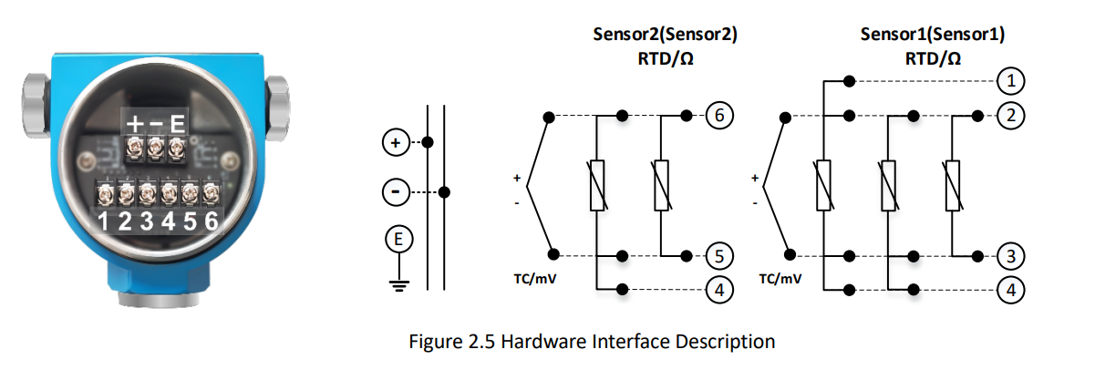
The NCS-TT105 terminal board is located behind the rear cover. Recommended wire gauge: 0.5 ~ 2.5 mm² (AWG 20 ~ 14).
2.1 RTD Wiring Diagrams
2-wire RTD wiring:
(1)---[RTD]---(2)
      |       |
(3)---+       +---(4)
(Jumper 1-3 and 2-4)
3-wire RTD wiring:
(1)---[RTD]---(2)
      |       |
(3)---+       +---(4)
(Jumper 1-3)
4-wire RTD wiring:
(1)---[RTD]---(2)
(3)-----------(4)
(No jumpers)
3. Bus Power and Loop Wiring
Warning: Do not connect the signal wire to the T+ test terminal. This will damage the protection diodes. If diodes are accidentally burnt, short circuit the T+ and – terminals as an emergency workaround.
3.4 LCD Diagnostic Indicators
| Icon/Code | Meaning | Action |
|---|---|---|
| Circular flashing | Normal communication | None |
| CONFIG_ERR | Configuration Mismatch | Check sensor type (Fun 22/23) |
| Fixed Value | Manual/Simulate mode | Check if loop is in Test mode |
4. Dual-Channel Configuration
4.2 PV Calculation Logic (SENSOR_MEAS_TYPE)
When SENSOR_MEAS_TYPE is configured for redundancy (193), the transmitter uses a state-machine logic: if SV_1 status becomes ‘Bad’ or ‘Uncertain’, the PV automatically switches to SV_2 to maintain process uptime.
| Setting Value | PV Formula | Application |
|---|---|---|
| 0 | PV = SV_1 | Single sensor, channel 1 primary |
| 128 | PV = SV_1 – SV_2 | Differential temperature |
| 192 | PV = (SV_1 + SV_2) / 2 | Average temperature |
| 193 | PV = SV_1, fallback to SV_2 | Redundant with hot standby |
5. Cold Junction Compensation Setup
CJC accuracy is critical for thermocouples. For precision applications, use RJ_TYPE = Sensor 2 with a Pt100 RTD on channel 2 to measure the terminal temperature more accurately than the internal sensor.
6. Field Calibration Procedures
Field calibration ensures the transmitter compensates for site-specific variables like lead wire resistance and environmental conditions.
6.1 Two-Wire RTD Zero Calibration (Fun 26)
Note: You must short the leads at the sensor end (not the transmitter terminals) to accurately compensate for the lead wire resistance.
- Short the RTD leads together at the sensor.
- Navigate to Fun 26 on the LCD using the [Z] and [S] keys.
- Press [M] to enter, then press [S] to start calibration.
- When “OK” appears, the lead resistance is zeroed out.
6.2 HART Zero and Span Trim (HartMPT)
For high-precision loops, use the HartMPT software to align the 4-20mA output with your master ammeter:
- Go to Calibration → Output Trim.
- Connect a precision multimeter in the loop.
- Input the actual mA reading into the software to adjust the D/A converter.
7. LCD and Local Operation
The NCS-TT105 supports full local configuration via three magnetic buttons (Z, S, M). No communicator is required for basic setup.
- Fun 22
- Fun 23
- Fun 25
- Fun 26
| Function Code | Parameter | Description | |||||
|---|---|---|---|---|---|---|---|
| Fun 03 | Unit | Change between °C, °F, K, °R | |||||
| Sensor Type | Select Pt100, Cu50, Type K, J, T, etc. | Wire Mode | Select 2-wire, 3-wire, or 4-wire | Lower Range | Set the 4mA point (Zero) | Upper Range | Set the 20mA point (Span) |
8. Explosion-Proof Installation Requirements
8.1 Flameproof (Ex d) Installation
- Ensure the enclosure cover is tightened until there is no gap.
- Use certified Ex d cable glands with at least 5 threads engaged.
- Do not open the cover in a hazardous area when the power is on.
8.2 Intrinsically Safe (Ex ia) Installation
- Must be powered through a certified safety barrier (e.g., Vo ≤ 30V, Io ≤ 120mA).
- Total loop capacitance and inductance must not exceed barrier limits.
9. Startup and Verification Checklist
Before leaving the site, verify the following:
- [ ] Physical: All covers tightened, cable glands sealed with weatherproofing.
- [ ] Configuration: SENSOR_TYPE matches the installed sensor.
- [ ] Loop Power: Voltage at terminals is between 11.5V and 45V DC.
- [ ] Calibration: 4mA and 20mA points align with the DCS range.
10. Troubleshooting Quick Reference
| Symptom | Possible Cause | Recommended Action |
|---|---|---|
| LCD No Display | Loop power < 9V / Reverse polarity | Check supply voltage and wiring polarity. |
| CONFIG_ERR | Sensor type mismatch | Verify Fun 22/23 settings match physical sensor. |
| Reading Drift | Lead resistance (2-wire) / EMI | Repeat Fun 26 calibration; check cable shielding. |
| CJC Error | Internal sensor failure | Switch RJ_TYPE to “Fixed” or use external Pt100 on Ch 2. |